In many areas with high groundwater levels, area-wide measures are required to regulate groundwater levels. In developed areas in particular, drainage pipes are laid to drain the excess water to the nearest watercourse without causing any damage.
The following pictures show the problem schematically:
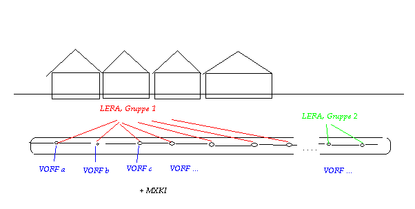
Longitudinal section of a drainage system in the road area
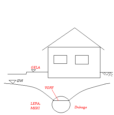
Cross-section of a drainage system in the road area
The implementation in a groundwater model created with SPRING is as follows:
VORF
The mesh nodes of the drainage are given a watercourse stage height whose value corresponds to the desired groundwater level (e.g. basement foundations - 0.80 m).
LERA
In contrast to a sump well, a polyline-related leakage (LERA, [m/TU]) is used for drainage. The affiliation and sequence of the nodes of a specific drainage line must be observed, as the "LERA" data is managed in groups. If discharge measurements are available for the drainage, the leakage coefficient can be calibrated by comparing the measured leakage rate and the leakage rate calculated by the programme. The calculated watercourse leakage rates can be imported into SPRING, for example, via Attributes  Import model data/result data...,(background file "aaa", "Leakage rates", desired attribute identification, e.g. Q-LK). The leakage rate (in m³/node/TU) at the individual drainage nodes can be determined with Attributes Edit nodes. By adding up the individual node rates, the total discharge rate in the drainage calculated by the model is obtained.
MXKI
To prevent the (empty) watercourse from infiltrating into the groundwater at a lower groundwater level, the possible infiltration rate at the associated nodes is set to the value 0.0 via the MXKI attribute.
MXKE
To limit the withdrawal rate due to technical constraints (max. discharge volume of the drainage), we recommend defining a maximum withdrawal at the receiving water node with the MXKE attribute (note the sign convention: A negative value must be entered here to limit the withdrawal rate). The unit for a polyline-related restriction is m³/TU/m, i.e. a total rate must be specified for the respective polyline (observe the node sequence). The final maximum value for the individual node is calculated in the programme by multiplying it by the proportional distance between the left and right neighbouring nodes.
Stand: 18.04.2025 | 